What the kernel's link boxes actually enclose — in pictures
Status: measurement only. No kernel, manifest or schema change. The boxes measured here are still the shipped
collision_geometryboxes; since #166 the kernel refines them withtight_geometry(26-DOP + exact hull), see the staged hull narrow phase. This page renders the geometry that the collision-primitive study (PR #157) argues in prose, and re-derives its fit numbers from the meshes independently.Everything below is
panda_mobile'scollision_geometry—panda_link1…panda_link7, the only links the C++ safety kernel places a primitive on. There is no base box and no gripper box (study §1).
Ground truth is robosuite 1.5.2's link<N>_collision mesh geoms — the same
meshes sim_sensor_bridge._body_collision_points samples — placed in the link
frame and compared against the half-extents and origin_xyz_rpy committed in
robots/panda_mobile/robot.yaml.
1. The headline
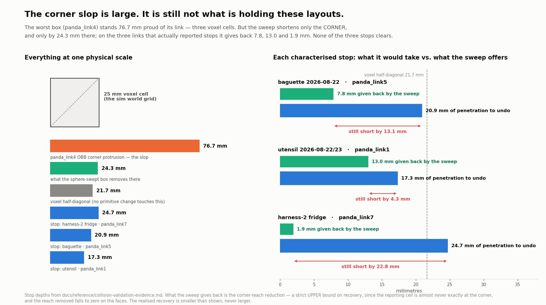
The worst box (panda_link4) stands 76.7 mm proud of its own link at the
corner — three voxel cells. The sphere-swept box only shortens the corner, and
on the three links that reported stops it hands back 7.8, 13.0 and 1.9 mm
against penetrations of 20.9, 17.3 and 24.7 mm. None of the three stops
clears — the study's §6 result, drawn to scale.
2. Per link: the box, the mesh, and the gap between them
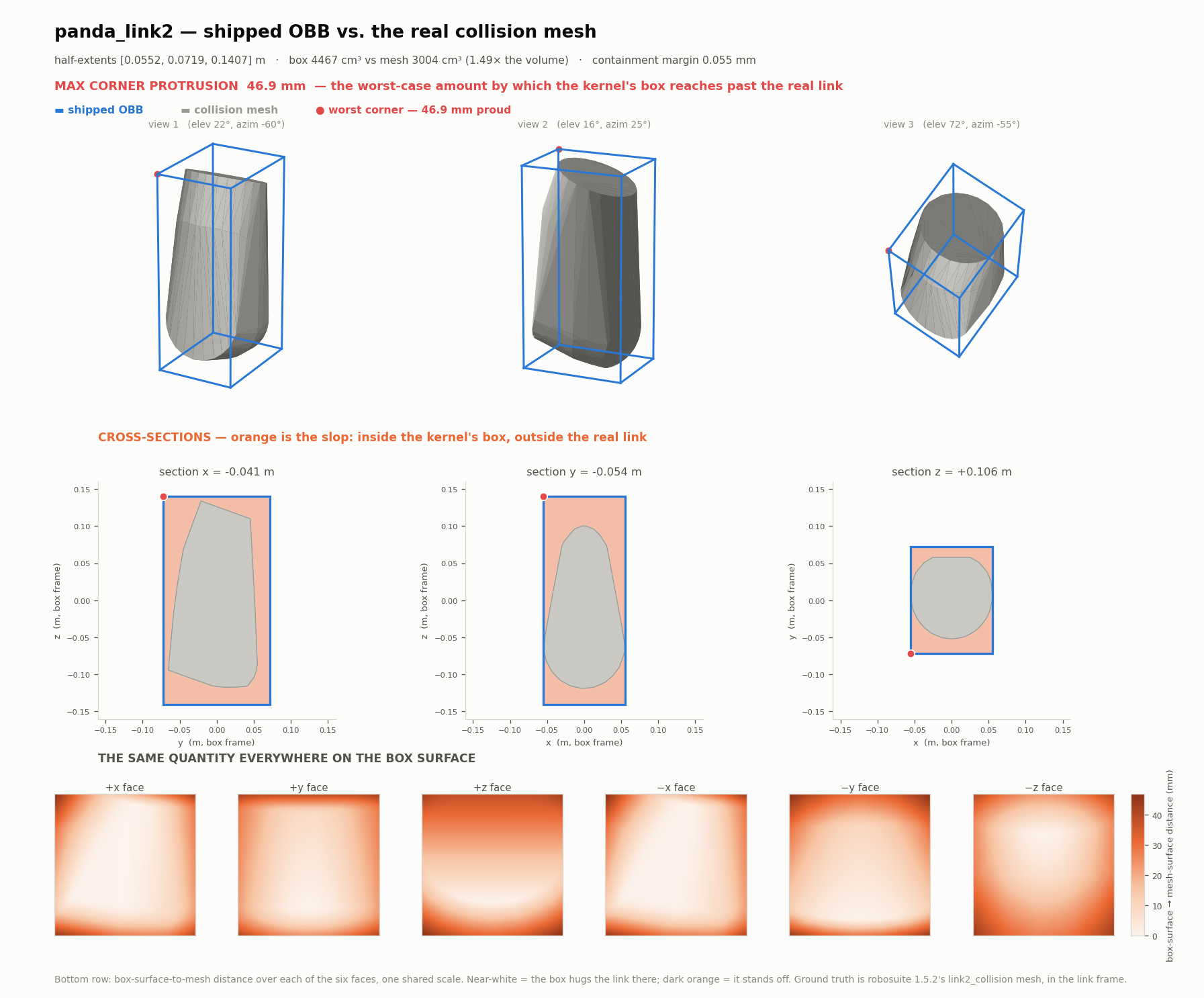
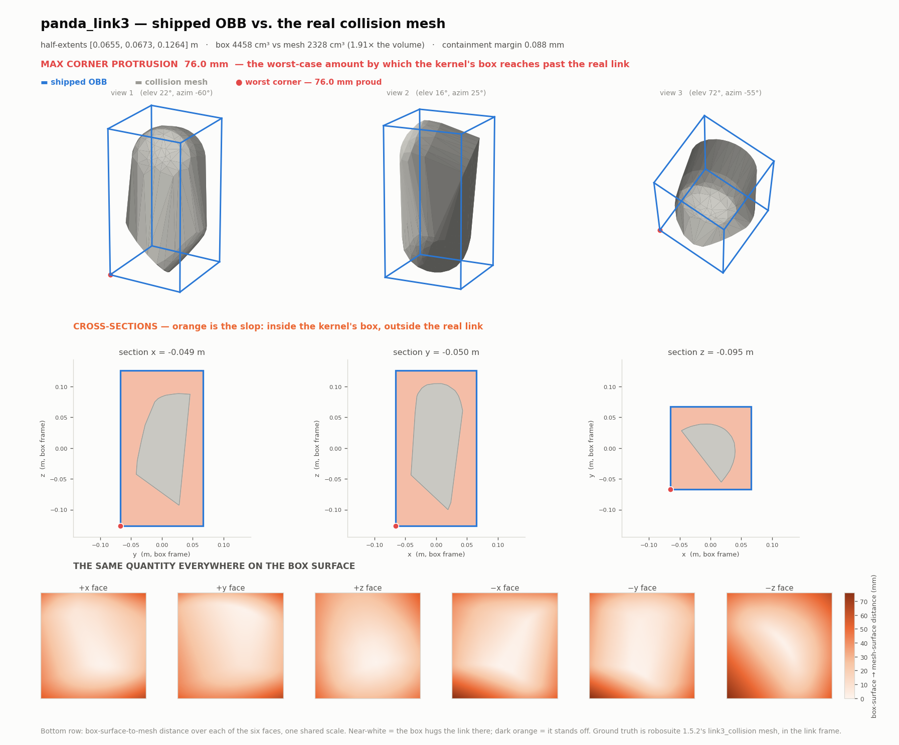
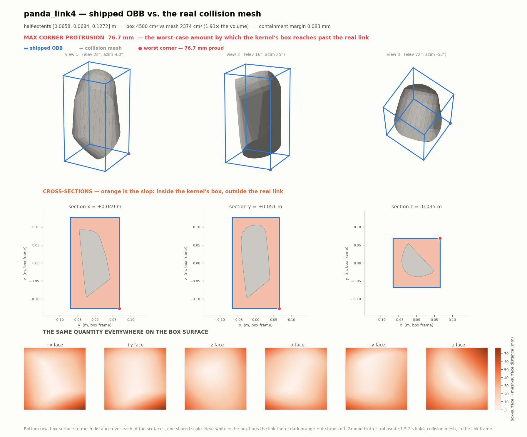
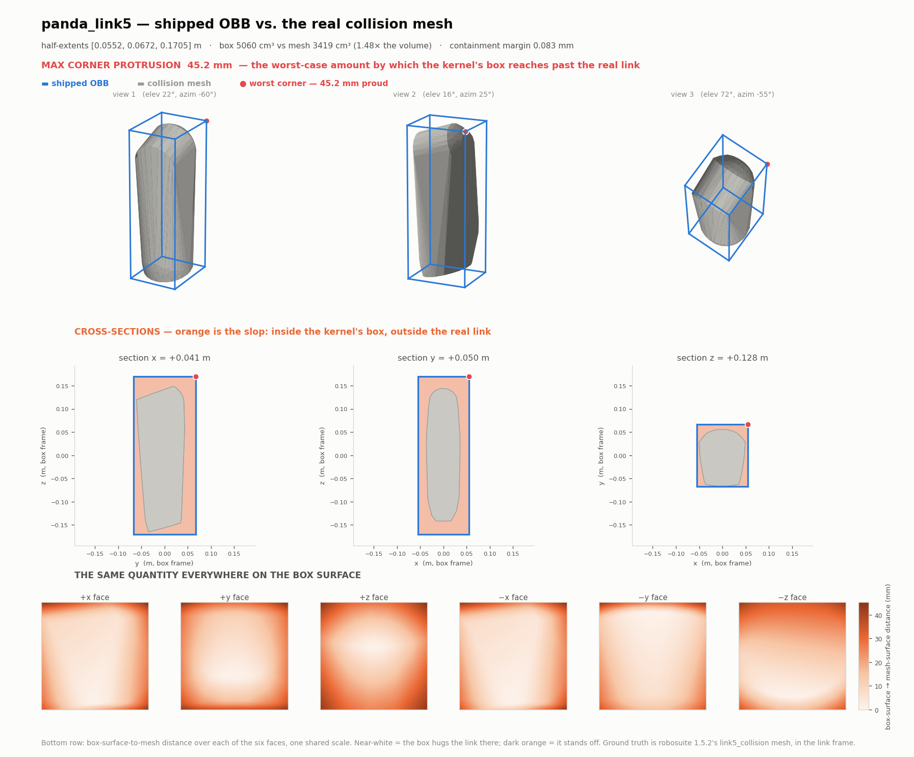
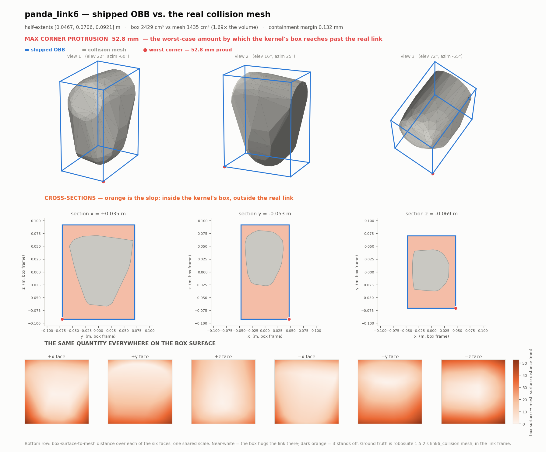
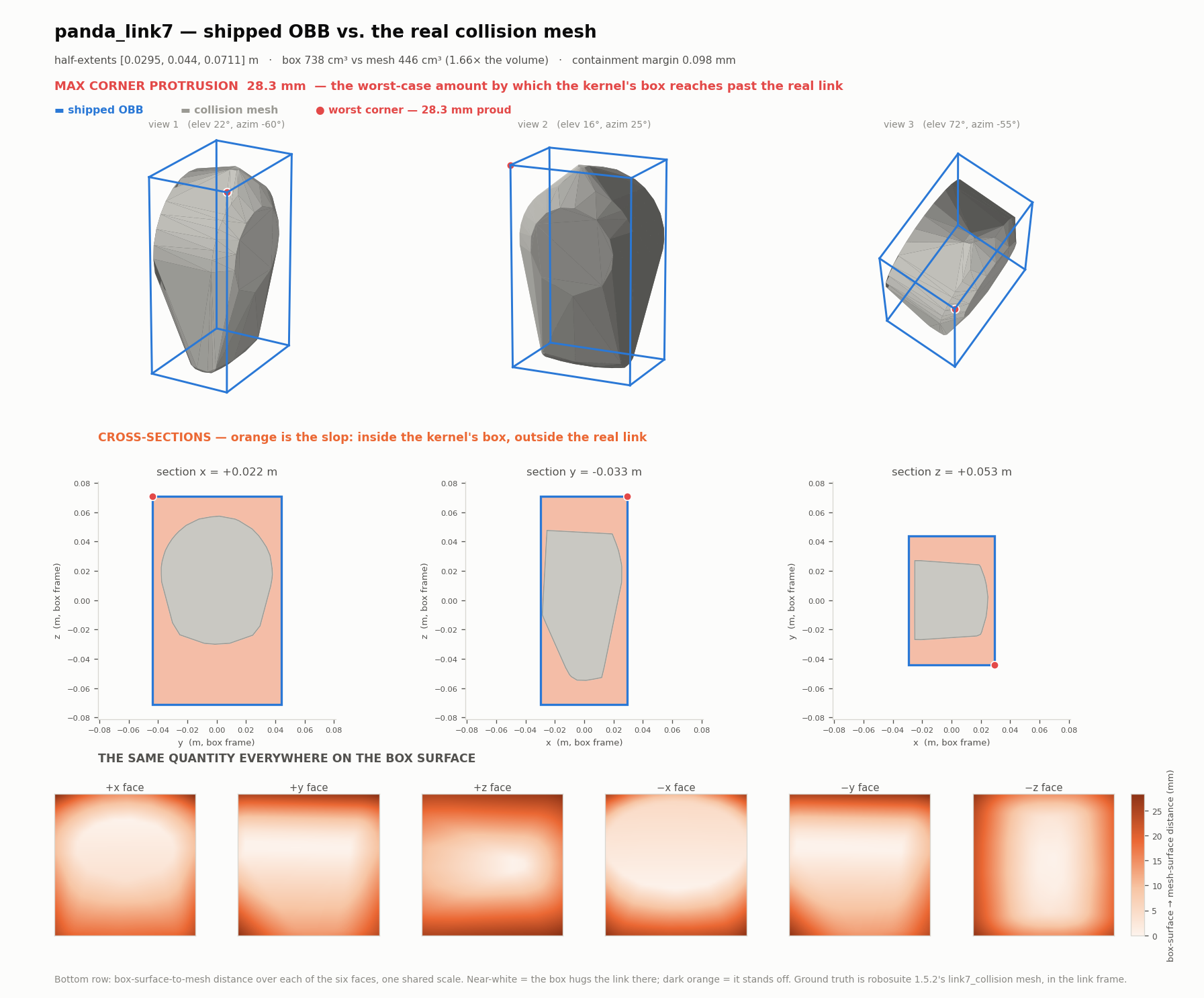
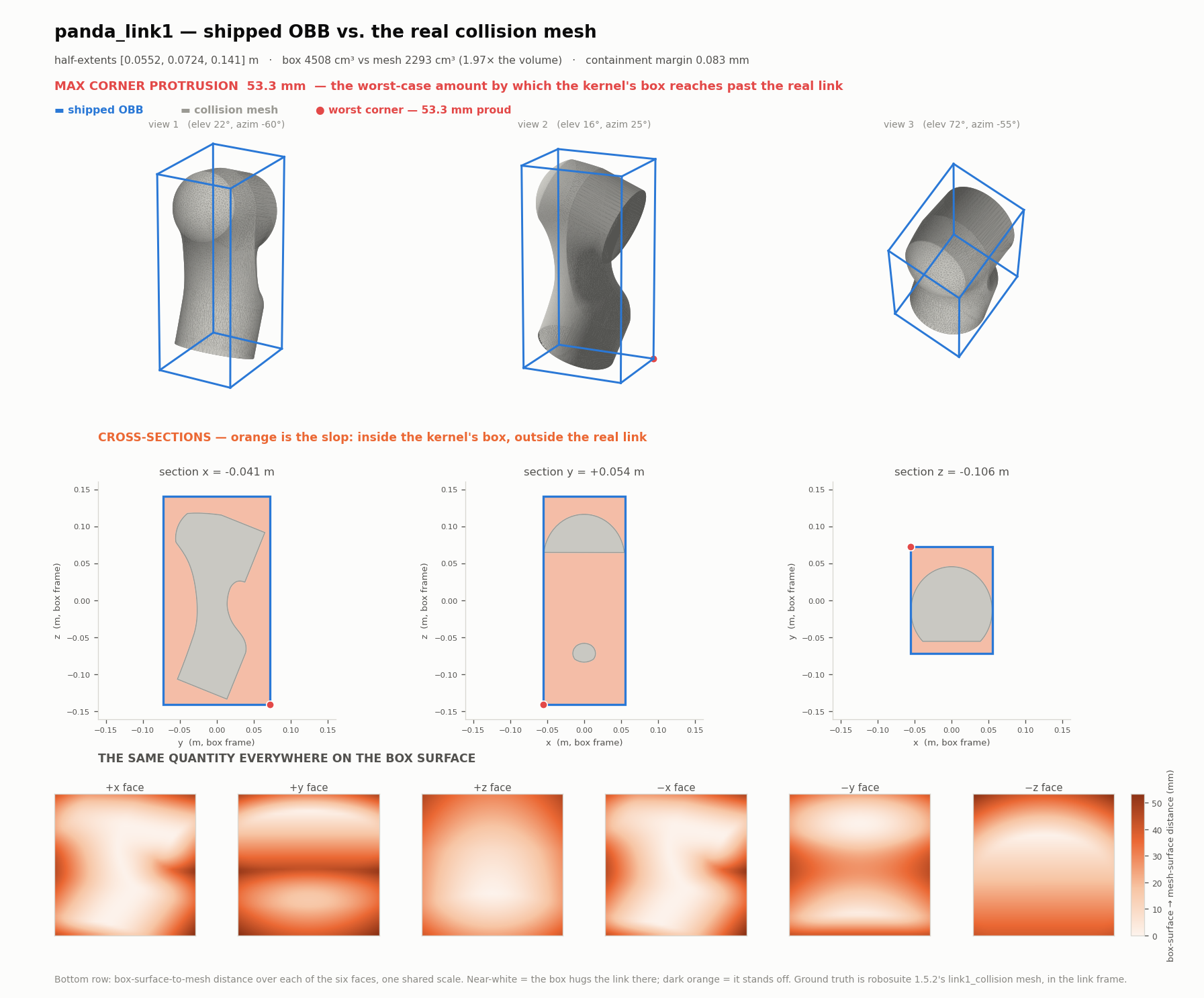
Each figure has three parts:
- top — the collision mesh inside the shipped OBB, from three viewing angles, with the worst corner marked;
- middle — three orthogonal cross-sections, with everything inside the box and outside the mesh shaded orange. That orange area is the entire subject;
- bottom — the box-surface-to-mesh distance sampled over all six faces on one shared scale. Near-white where the box hugs the link, dark where it stands off.
| link | max corner protrusion | box ÷ mesh volume | containment margin |
|---|---|---|---|
panda_link1 |
53.3 mm | 1.97× | 0.083 mm |
panda_link2 |
46.9 mm | 1.49× | 0.055 mm |
panda_link3 |
76.0 mm | 1.91× | 0.088 mm |
panda_link4 |
76.7 mm | 1.93× | 0.083 mm |
panda_link5 |
45.2 mm | 1.48× | 0.083 mm |
panda_link6 |
52.8 mm | 1.69× | 0.132 mm |
panda_link7 |
28.3 mm | 1.66× | 0.098 mm |
Two things the table cannot show:
The maximum is at an exact box corner on all seven links. The face-distance panels show it: the faces are near-white (fitted tight to within tens of microns) and the slop piles up entirely in the eight corners.
panda_link1 is the odd one out. Its +y face panel shows a dark band,
not dark corners, because link1 is the one genuinely non-convex link in the set
(30 % convex-hull excess — the other six collision meshes already are their own
convex hulls). Its cross-section shows the concavity directly.
3. The sphere-swept box: faces held, corners in
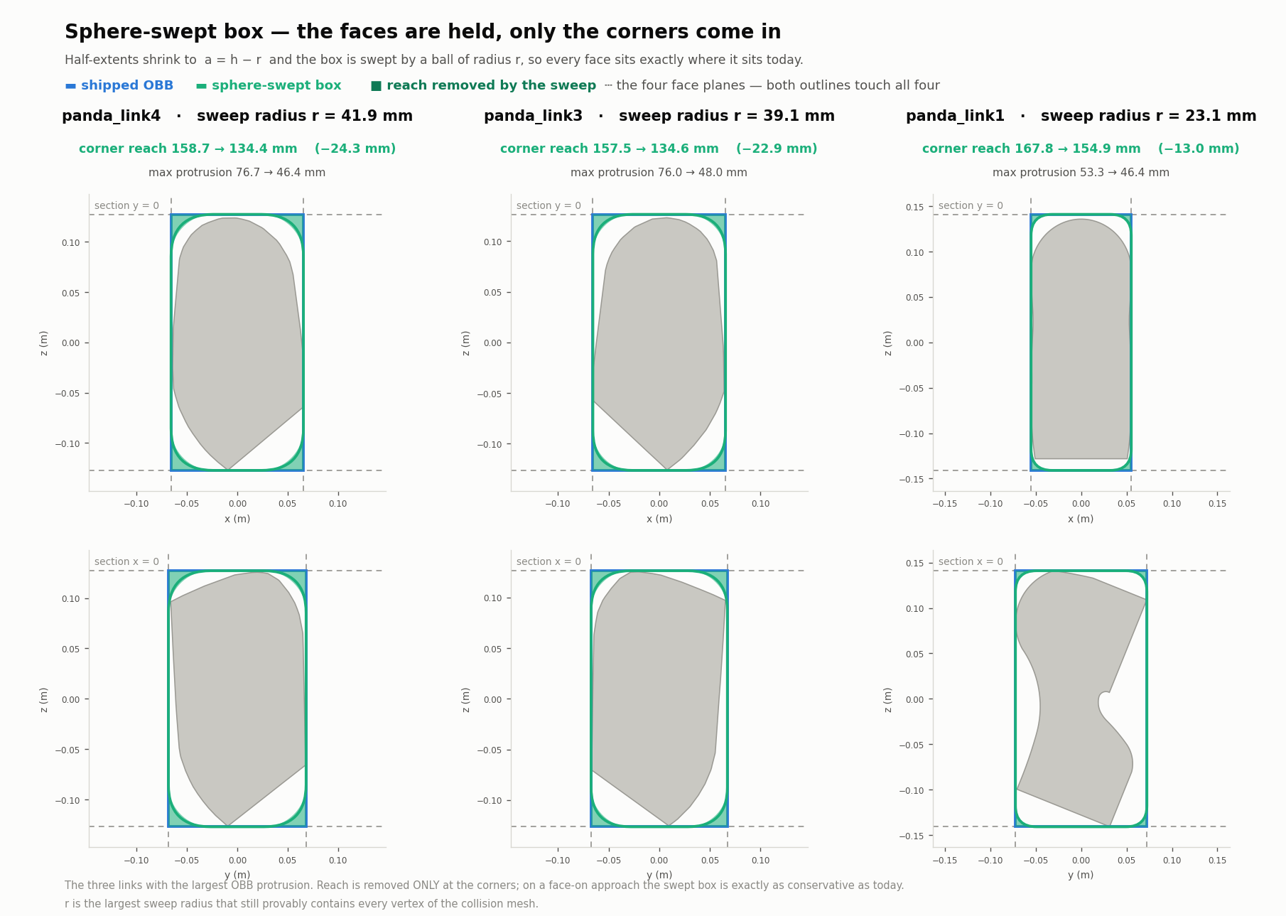
The construction is a = h − r swept by a ball of radius r, so every face
plane stays where it is today. The dashed lines in each panel are the four face
planes: both the blue rectangle and the green rounded outline are tangent to all
four, and only the corners move, inward — the shaded green slivers.
r is the largest sweep radius that still provably contains every vertex of
the collision mesh, found by bisection at 0.1 mm and verified by containment,
not by an optimiser's tolerance.
| link3 | link4 | link1 | |
|---|---|---|---|
sweep radius r |
39.1 mm | 41.9 mm | 23.1 mm |
| corner reach | 157.5 → 134.6 mm | 158.7 → 134.4 mm | 167.8 → 154.9 mm |
| reach removed | −22.9 mm | −24.3 mm | −13.0 mm |
Reach removed on the remaining links: link2 −11.0, link5 −7.8, link6 −5.1, link7 −1.9 mm.
4. Where this disagrees with PR #157 — and why the disagreement matters
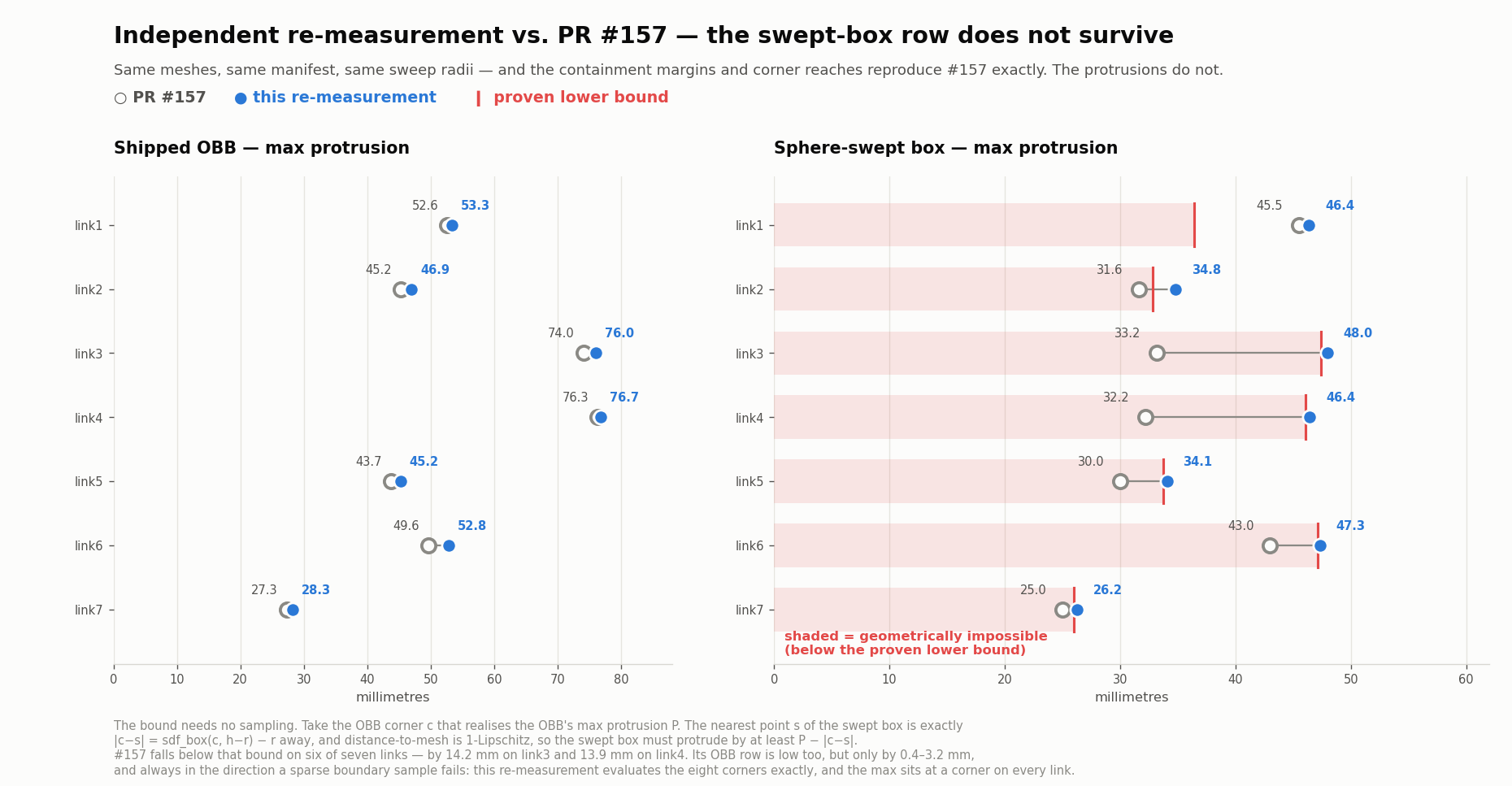
This re-measurement reproduces #157's containment margins exactly on all
seven links (0.083 / 0.055 / 0.088 / 0.083 / 0.083 / 0.132 / 0.098 mm), its
OBB corner reaches exactly, and its sweep radii to the resolution #157
reported them. Same meshes, same manifest, same frames. The swept-box corner
reaches differ by up to 0.5 mm (link4 134.4 here vs 134.8; reach removed link1
−13.0 vs −12.9, link2 −11.0 vs −10.8, link5 −7.8 vs −7.5, link6 −5.1 vs −4.7)
because r is bisected at 0.1 mm here and swept at 1 mm there, so each r here
is slightly larger.
The protrusion columns do not agree:
| link1 | link2 | link3 | link4 | link5 | link6 | link7 | |
|---|---|---|---|---|---|---|---|
| OBB — #157 | 52.6 | 45.2 | 74.0 | 76.3 | 43.7 | 49.6 | 27.3 |
| OBB — here | 53.3 | 46.9 | 76.0 | 76.7 | 45.2 | 52.8 | 28.3 |
| swept — #157 | 45.5 | 31.6 | 33.2 | 32.2 | 30.0 | 43.0 | 25.0 |
| swept — here | 46.4 | 34.8 | 48.0 | 46.4 | 34.1 | 47.3 | 26.2 |
| proven lower bound | 36.4 | 32.8 | 47.4 | 46.1 | 33.7 | 47.1 | 26.0 |
The OBB row is a sampling difference and is not interesting. #157 sampled 12 000 points on the primitive boundary; this measurement evaluates the eight corners exactly in addition to a face grid. Since the maximum provably sits at a corner on every link, the exact evaluation is the tighter and more correct number, and the gap is one-directional and small (0.4–3.2 mm).
The swept-box row is a real error in #157, settled without sampling. Let c
be the OBB corner realising the OBB's max protrusion P, and
S = Box(h − r) ⊕ B(r). The point of S nearest to c is exactly
|c − s| = sdf_box(c, h − r) − r away, and distance-to-a-mesh is 1-Lipschitz,
so S must protrude by at least P − |c − s| — the italic row above.
#157's swept-box figures fall below that bound on six of seven links — by
14.2 mm on link3 and 13.9 mm on link4 — and fall below it even when the bound is
computed from #157's own (lower) OBB numbers on links 3, 4, 5 and 6. Every
value measured here sits just above the bound, the expected signature of a
boundary sampler finding the true maximum.
The mechanism is #157's swept-boundary sampler: it pushed box-surface points
along random outward directions and kept only those landing at distance
exactly r, under-covering the rounded corner shell — precisely where the
maximum lives, and worst on the links with the largest r (link3 and link4, at
39 and 42 mm). This measurement bisects along a 24 000-direction set with the
eight corner directions inserted explicitly.
What this changes. It makes the swept box less attractive: the real tightening on link3 is 76.0 → 48.0 mm (37 %), not 74.0 → 33.2 mm (55 %). The study's §6 recovery analysis is untouched, because that argument runs on corner reach, which reproduces exactly — so §8.1's recommendation stands.
5. Reproducing these
Inputs, environment and method are as in the study's §9, with these differences, all of which move the numbers in the conservative direction:
- Mesh placement. Vertices come from
mesh_vertplaced by the geom transform only. MuJoCo recentres asset vertices at compile time and folds the compensating transform into the geom frame — heregeom_pos/geom_quatcome out exactly equal tomesh_pos/mesh_quat, so applying both double-counts it and puts the mesh 80–180 mm out of frame. Verified against the raw STL assets to 7 × 10⁻⁹ m. - OBB boundary sampling. A 60 × 60 grid per face (21 600 points) plus all 12 edges and, decisively, the 8 corners evaluated exactly.
- Swept boundary sampling. Bisection along a 24 000-point Fibonacci
direction set plus the 8 corner directions, solving
sdf_box(q, a) = rto machine precision — the swept body is star-shaped about its centre, so this is exact per direction. - Sweep radius. Swept at 0.1 mm rather than 1 mm.
- Containment. Every mesh vertex checked; the primitive is convex, so
containing the vertices proves containing
conv(vertices) ⊇ mesh.
Environment: workspace .venv — numpy 2.2.6, scipy 1.17.1, trimesh 4.12.2,
shapely, mujoco 3.8.0, robosuite 1.5.2, matplotlib 3.10.9. CPU only; no GPU work
is involved.
See also
- Collision-primitive study (PR #157) — the geometry argument, the full candidate table, and the cost/safety-WG analysis.
- Collision-stack validation evidence — the failure census the three characterised stops come from.